Introduction:
Gearing of Altazimuth telescope:
Stepper motors:
Electronics:
Guiding:
Pulse Width Modulation (PWM):
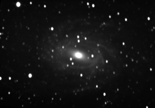
This page serves both as a record of problems that I have encountered whilst building and tweeking the telescope and as a possible source of help for anyone reading these pages who may be encountering similar issues. All issues trace back from the results at the camera and it is from here that my efforts to obtain better quality images and hence, data, have initiated. The image below is a 27 minute composite of NGC6744. The reader will see immediately that the stars are ellipsoidal. This could be due to a wide variety of factors, from optics through mechanics and electronics to software.
First and foremost acknowledgement is due to Mel Bartels for his SCOPE program that drives the scope motors and the excellent help files that he has put together.
Gearing of Altazimuth telescope:
While at prime focus you can get away with a lot of deficiencies with drive gears, such as, backlash and inconsistencies in the meshing of teeth, I thought it wise to invest in a set of zero backlash gears that I could afford and ones that are well made. I chose to use the "Expert" quality Girard "Dynabox" gears, made in France. I chose to use two 30:1 reduction gears, one mounted on the other so as to get a reduction of 900:1. This is at the extreme low end as a better reduction would have been around 1500:1 if only to have the stepper motor spin faster whilst microstepping and to remove any jitter as it rotates about one and a half times per minute. However, the main reason for my choice was to speed up during halfstepping of the drive motors. When the need for greater magnification whilst tracking arises, this arrangement is about the best I can do.
These gearboxes run at 0.5 arcmin backlash and it is possible to set them at zero but this is a strain on the motors. At best, then, one can set one of the Dynaboxes to zero and the other to 0.5 arcmin i.e. connect the latter to the motor and the zeroed one to the output of the first to minimize stress on the stepper motor.
I recently discovered an anomaly in the azimuth motor halfstepping speed ... What the Bartels method says to do to get the fullstep (stepper motor) sizes right for slewing and microstepping accuracy is start with an estimate of 3 arcseconds per fullstep size then "The altitude is measured by using a precision level to set the tube horizontal, resetting alt to 0, then moving the scope via the motors until the precision level indicates the tube is exactly vertical. The ratio between the displayed alt and 90 degrees is the amount to adjust the step size by. Similarly, one complete turn in azimuth can be used to adjust the azimuth step size". I tried this method and got different results for the alt and az motors. Namely 7.201234 for the Alt and 4.76256 for the Az stepsizes. I lived with this for a while but was never happy with the amount of drift I was getting, especially in the azimuth. Not only that but the accuracy in finding an object was infuriating. It occurred to me that since I had the wonderful gearing I should be able to calculate the stepsizes. What I got was 7.2 for the Alt motor and the same for the Az motor. I still wondered why the two values differred in practice. On doing a reverse calculation with the Az motor stepsize I discovered that the resulting gear ratio was very close to 1350 so I checked the ratios of the Az greaboxes and found that one of them was 45:1. Further checking revealed that the company had sent me the wrong gearbox with the right label. Having this sorted out, in my mind at least, I was able to make the calculation and come up with a fullstep size of 4.8 for the Az motor. Now the scope tracks very well with very little drift. The drift I get is only due to tiny imperfections in the 'horizontality of the mount'.
To calculate the stepsizes: combined-gear-ratio (30 x 30:1) = 900 x stepper fullsteps e.g. 200 = 180000 fullsteps per 360 degrees. divide how many arcsecs in 360 degrees by total fullsteps required
i.e. 360 x 3600 = 1296000. So 1296000/180000 = 7.2 arcsecs per fullstep.
In other words:
129600/RS
Stepper Driver
Dome Driver
Remote Switching
When configuring a telescope for visual work there is a lot of room for error, guiding can be done using very coarse equipment but, when relying on light to fall on a ccd chip, any movement off the pixels by a star will result in trails.
When following a patch of sky for more than a minute, in particular near north, south and around the zenith the sky tends to rotate very quickly. If looking east, at say 30 degrees above the horizon, there is little rotation of the sky but the rotation accelerates as we step higher in altitude. Guiding, i.e. using a guide camera mounted on a guide scope, which in turn is mounted on the main scope, needs to compensate for alt drift and az drift. There is a problem, however, the mount of the guide scope with it's camera is subject to minute flexure which is negligible at low altidudes, up to 45 degrees but can cause trouble at higher altitudes when the strains start to affect the position of the guide scope. Very minute but nonetheless troublesome as the guide scope comes more and more out of alignment with the main scope as the altitude rises. It tries to overcompensate resulting in ever increasing drift. Some cameras like the QSI range have a built in mirror right at the periphery of vision of the main mirror. It doesn't gather much light to send to the guide camera, which in this case is mounted on the main camera and the guide star chosen as the object to track is most often not in view of the main camera. This works well enough at low altitudes again but when the sky is rotating, adds another guiding variable to the mix. The result is more drift. I have not come up with a solution for this yet but I think that guiding off a star very close to the centre of the ccd chip should solve the problem
Experience and theory will eventually indicate that the star patterns falling onto the ccd chip will rotate 180 degrees in 12 hours when using an AltAzimuth arrangement. If one is doing exposures of more than one minute and pointing near the celestial poles or near zenith, this rotation of the image is very pronounced. However, if pointing low to the east or west there is little indication that the field is rotating. I procurred a 2 inch Pyxis derotator ( a 3 inch would have been many times better but the cost is prohibitive) and had a mounting plate made up by Nick Booth so I could fit a QSI 500 camera onto it. The Pyxis2 is quite coarse as it's stepper motor has only 48 fullsteps and one can hear the rotator gears as they move the camera around. The results, for ccd photography, are often little jumps from one position to another marring the images. Since the Bartels Scope.exe program has a facility for pulsing out to a derotator and since it has a very fine resolution, I decided to modify the Pyxis by disconnecting it from it's own electronics and software. I made up a little driver and connected it directly to the parallel port pin outputting the pulse from the Bartels program. The result was a much finer stepping resolution than Pyxis could offer with their setup.
I have found that even with derotation there are problems for prolonged exposures. The derotator rotates only around the focusser but the sky rotaes around the north and south celestial poles; two differing rotations so the derotation probably, can never be exact. The obvious solution is to use an equatorial mount and throw away the derotator, however, there will be changing forces/strains on the focusser as the scope on such a mount moves around the sky. This, I fear, will also add guiding errors to the system so I'm sticking to the AltAz system and putting up with problems that I have gotten used to.
The last thing I expected was to have to completely re-jig the PWMs in order to eliminate the elongations of stars in my images but this was indeed the case.
I discovered, while I was tightening up some slack in the drive system that the stepper motor was not microstepping at all. It was fullstepping and while microstepping signals were being sent to the motor it simply wasn't seeing them so that, while the stars moved across the CCD screen the scope was constantly catching up and then overshooting. Some measurements using a laser pointer mounted on the rotor showed that the PWMs were wrong and that I wasn't allowing enough delay for the motor to see the signals.
Mel Bartels' Scope.exe software comes with a huge amount of information and help. In particular, some information about Pulse Width Modulation to extend the gear ratio reduction by means of electronics. I generally ran my telescope on 20 microsteps per fullstep of the stepper motor to get a reduction of 900 x 200 x 20 = 3.6 million :1. The stepper motor has 200 steps per revolution and, in this case, 20 microsteps in between each fullstep; hence the arithmetic. It is possible to double this to 7.2 million as the software can handle 40 microsteps per fullstep. At this reduction the gearing has a resolution of 0.18 arcsecs per microstep.
Generally, the formula for ascertaining the theoretical PWMs for each microstep should result in a sinewave scattergraph if you map all of them onto a graph but, as I found out, manufacturing and stepper motors don't pre-empt theory. Values can be totally inconsistent with theory.
The theory goes something like this:
For 10 microsteps per fullstep the rotor needs to be positioned on the centre of winding 1 at start so we give it 100% while giving winding 2 zero.
then for the next position we need to be 1/10th of the way over. Theory says that the rotor tooth will feel the field of the winding at a strength of 1/D^2 (where D is the distance of the rotor tooth from the winding) Since the windings work in pairs the rotor is affected by the actions of both.
Thus to accommodate for both windings we say: for the first microstep [sqrt of 1/9] (then multiply by 100 to get percentage of charge required for the winding, winding 2 ) and for microstep 2 we say [sqrt 2/8] and so on.
The windings are theoretically as follows:
winding 1 winding 2
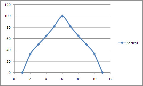
PWM[0] 100 : 0
PWM[1] 100 : 33
PWM[2] 100 : 50
PWM[3] 100 : 65
PWM[4] 100 : 82
PWM[5] 100 : 100
PWM[6] 82 : 100
PWM[7] 65 : 100
PWM[8] 50 : 100
PWM[9] 33 : 100
As is obvious from the graph, the PWMs that work for my motors don't create a sine curve.
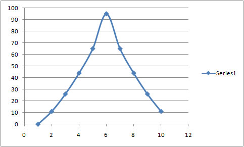
My adjustments to the PWMs so that I got ten evenly spaced microsteps are as follows:
winding 1 winding 2
PWM[0] 100 : 0
PWM[1] 100 : 11
PWM[2] 100 : 26
PWM[3] 100 : 44
PWM[4] 100 : 65
PWM[5] 100 : 95
PWM[6] 65 : 100
PWM[7] 44 : 100
PWM[8] 26 : 100
PWM[9] 11 : 100
Funnily enough if a graph of plain 0/10 x 100, 1/9 x 100, 2/8 x 100 etc is drawn up it looks remarkably like this:
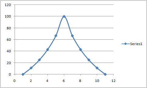
Somehow my motors are doing the
trigenometric conversion. So the
theoretical trig version PWM table looks like this
below:
winding 1 winding 2
PWM[0] 100 : 0
PWM[1] 100 : 11
PWM[2] 100 : 25
PWM[3] 100 : 43
PWM[4] 100 : 67
PWM[5] 100 : 100
PWM[6] 67 : 100
PWM[7] 43 : 100
PWM[8] 25 : 100
PWM[9] 11 : 100