Field Lines
Field lines are invisible in the final image but their construction is
necessary for the location of 1-DE s In the image below a set of vertical
dots have been placed 10 units apart along a vertical field line which
is parallel to the vertical edge of the frame. A second set of dots extend
along a field line which subtends the horizontal frame at about 20 degrees.
-
The two sets of dots then follow the rules for interference and a field
is created.
-
The position of each dot is dependent on only two others, thus in
the image
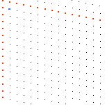 the two dots immediately below and to the right of the dot in the top left corner
control the position of the blue dot so that a distance of 10 units is maintained
between them and the blue dot. The distance between dots correlates with the trellis
rule such that dots in the same field line will always be at constant separation.even
though the trellis is scissored open or shut. The general equation for dealing
with straight field lines in this manner. Where H is constant And Y1 & X2
are co-ords for related dots.
[X3 , Y3] = [(H2 -
Y21)1/2 , (H2 - X22)1/2]
gives us the position of the next dot in the row.
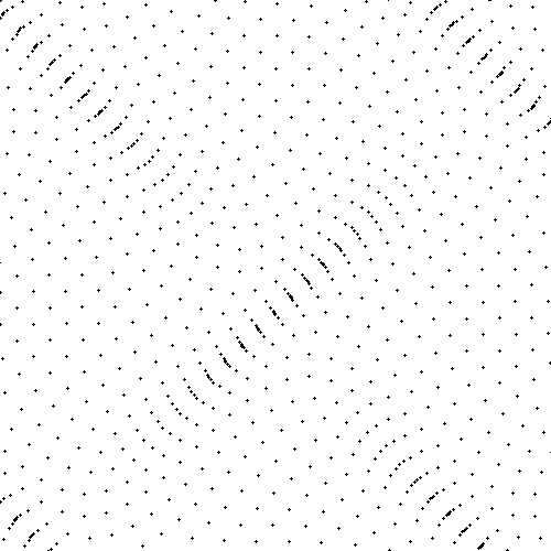
More complex fields can be set up by interfering field lines derived
from sine or parabolic functions.A simple parabolic curve ¦
(x) = x2 can be made to interfere
with itself at varying phase angles and at varying directions to produce
some quite remarkable field lines
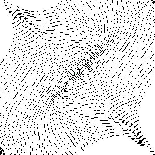
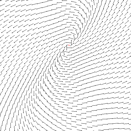
The two lower fields show not only the grid spacings and phase relations
of interfering waves but now they are at the second stage of creation since
representational lines have been added. The lines merely indicate the angular
relationship of that part of the field to its centre. Later on 1-Dimensional
elements (1-DEs) are overlayed where the 'representational lines' are.
(See
Artworks)
The general equation for evaluating line integrals is of the form
? ¦
x(s), y(s)]ds
Projects Index


marek@panetix.com

Last Revised: 30/12/99

 the two dots immediately below and to the right of the dot in the top left corner
control the position of the blue dot so that a distance of 10 units is maintained
between them and the blue dot. The distance between dots correlates with the trellis
rule such that dots in the same field line will always be at constant separation.even
though the trellis is scissored open or shut. The general equation for dealing
with straight field lines in this manner. Where H is constant And Y1 & X2
are co-ords for related dots.


![]()
![]()